Edge banding machine mechanism debugging (3)-Gluing component
Edge banding machine Gluing component
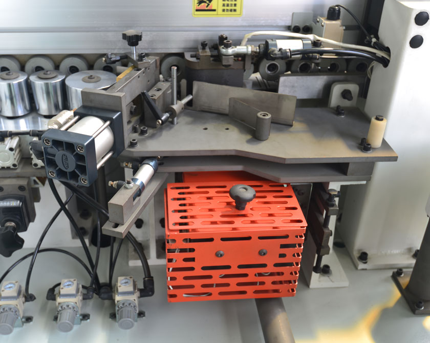
1、 Introduction to component names
The function of the gluing mechanism is to heat and melt the hot melt adhesive, apply the melted adhesive to the special edge sealing surface of the wooden board, attach the edge sealing strip to the glued wooden board, and cut the edge sealing strip. Mainly composed of rubber roller components and limit devices. 2. Limit device. 3. Limit device. 4. It consists of a cutting component, a feeding component, a gluing panel, etc.
2、 The operational process of the institution
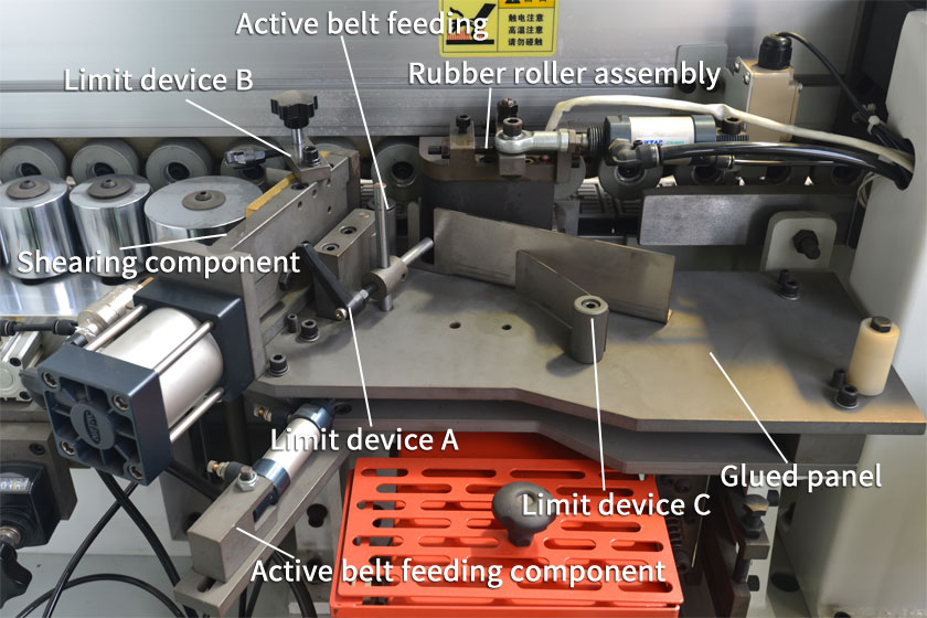
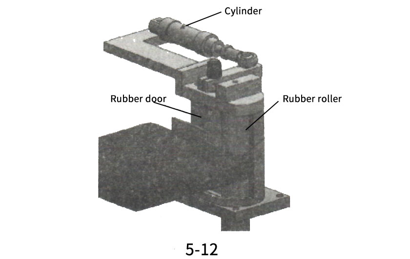
When the board enters the gluing mechanism through the travel switch, the cylinder of the glue roller assembly (as shown in Figure 5-12) opens the glue door, and the glue roller rotates the hot melt glue up. When the wooden board follows the chain board through the glue roller assembly, it sticks the glue onto the surface of the tape to be sealed.
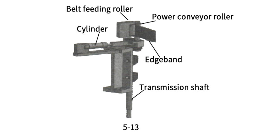
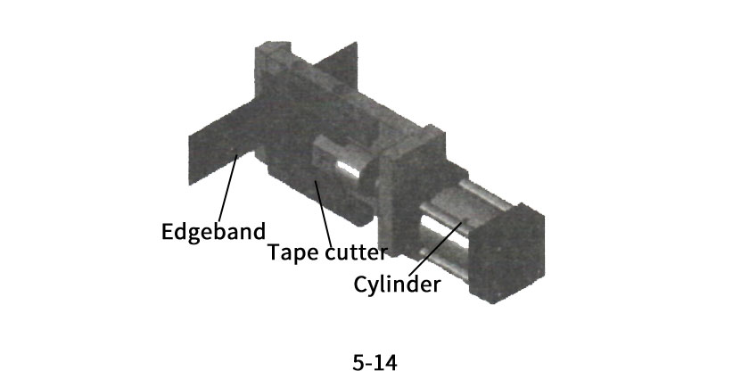
The belt feeding component works, and the cylinder pulls the power belt feeding rod into the belt feeding rod. The two belt feeding rods clamp the belt, and the transmission shaft transmits the power to the power belt feeding rod, rotating the edge banding belt onto the coated plate. After the board is completed (as shown in Figure 5-13), the cylinder of the belt cutting component begins to move (quickly push the belt cutting knife forward as shown in Figure 5-14), cutting the belt, and the gluing mechanism completes the action. Loop like this.
3、 Debugging method of the mechanism
The heating adhesive coating includes some adjustment mechanisms that can be adjusted to achieve a uniform and even thickness of the adhesive layer applied to the wooden board, ensuring the best edge sealing effect.
The adjustment of the adhesive layer includes four aspects: the adjustment of the contact pressure between the adhesive roller and the wooden board, the adjustment of the thickness of the adhesive layer, the adjustment of the adhesive output, and the adjustment of the verticality of the adhesive roller on the wooden board.
(1) Adjusting the thickness of the adhesive layer
To ensure uniform thickness of the adhesive layer applied to the wooden board, the screw ball shown in Figure 5-15 can be used; Adjust.
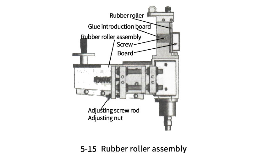
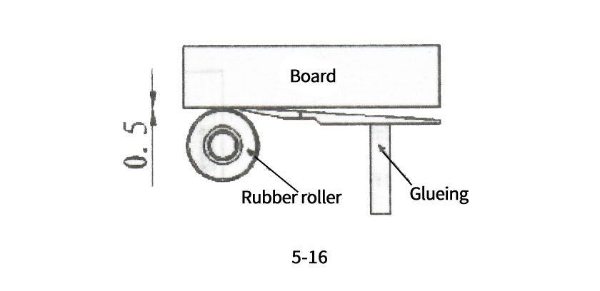
The specific adjustment method is to first loosen the screws and adjust the vertical distance between the working surface of the adhesive introduction board and the edge sealing surface of the board to 0 Between 1-0.5mm (as shown in Figures 5-16).
Turn on the conveyor belt function and heating adhesive function of the edge banding machine, and use appropriately sized wooden boards for trial edge banding. Check the thickness of the adhesive layer on the wooden board after edge sealing. If the adhesive is stuck to the upper and lower sides of the board, it indicates that the adhesive amount is too large and needs to be reduced; If there is no glue on the board, it indicates that the amount of glue is too small. Just increase the amount of glue.
If the adhesive layer is too thin, the bonding of the edge band is not strong, and the screw increases the gap between the guide and the wooden board. On the contrary, if the adhesive layer is uneven and the bonding is not strong after tearing off the edge banding, the gap between the guide and the wooden board can be reduced by adjusting the screws. By repeatedly adjusting the gap between the guide and the wooden board, the thickness of the adhesive layer can be achieved to a satisfactory effect.
(2) Adjustment of adhesive amount
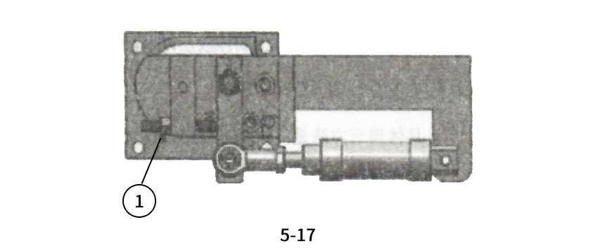
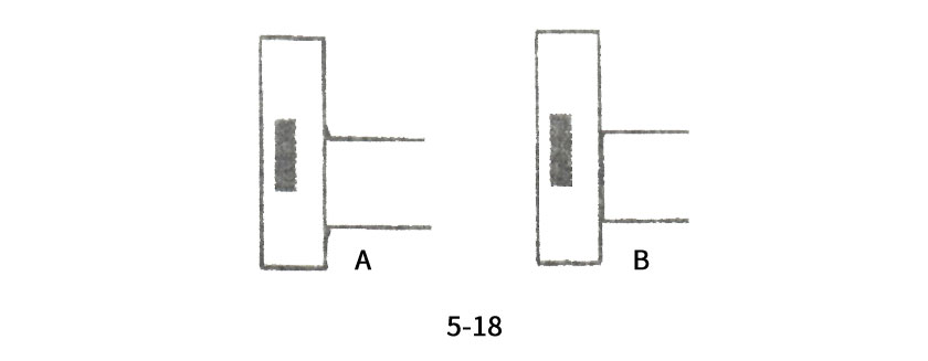
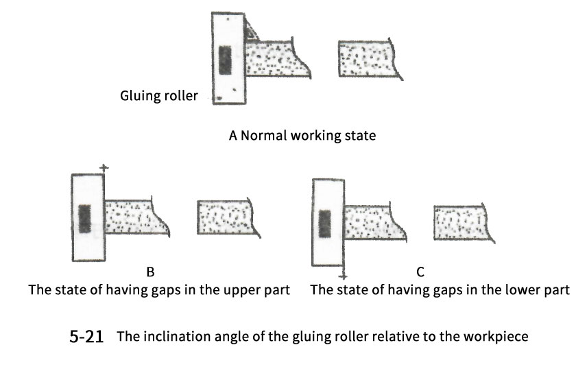
As shown in Figures 5-17, adjusting the tightness of the screw ① can adjust the daily glue output during the application process. When the screw rod is turned clockwise, the distance from the top to the adjustment screw rod becomes shorter when the cylinder is working, the working stroke of the cylinder becomes shorter, the gap between the rubber door and the rubber roller becomes smaller, and the amount of glue applied becomes smaller; When turning the nut counterclockwise, the side where the adjusting screw is pushed becomes shorter, the gap between the rubber door and the rubber roller becomes larger, and the amount of glue applied increases. When it is found that the adhesive layer on the wooden board after edge sealing overflows, it indicates that there is too much adhesive produced. The gap between the front end of the screw rod and the connecting rod should be reduced; On the contrary, if a gap can be seen between the edge banding strip and the board after edge banding, it indicates that the adhesive output is insufficient and the gap between the front end of the screw rod and the connecting rod needs to be increased. The relationship between the thickness of the adhesive layer and the amount of adhesive produced. When the gap between the adhesive roller and the wooden board is small but the amount of adhesive produced is large, there will be a phenomenon of adhesive overflow on the upper and lower surfaces of the wooden board as shown in Figure 5-18, 2; When the gap between the gluing roller and the wooden board is large and the amount of glue produced is small, the phenomenon of incomplete gluing as shown in Figure 5-18, B, will occur. At this point, the thickness and adhesive output of the adhesive layer can be comprehensively adjusted to achieve satisfactory results.
(3) Adjustment of contact pressure between gluing roller and wooden board
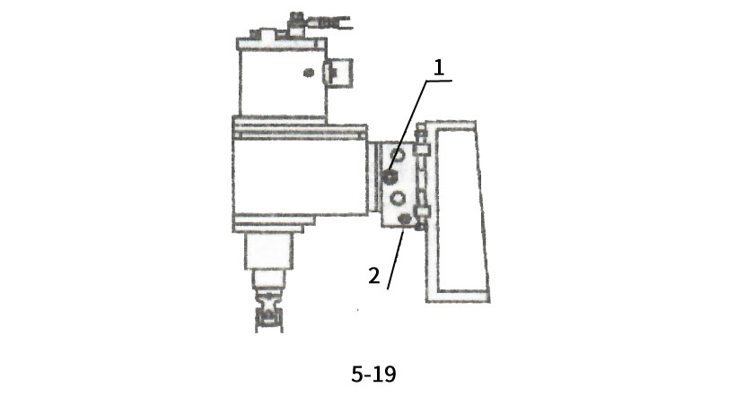
Adjusting the contact pressure between the gluing roller and the board can ensure that the glue adheres more firmly to the board, making it easier for the glue to penetrate into the board. Adjustment method: As shown in Figure 5-19, the pressure of the gluing roller on the wooden board can be adjusted through screw 2. The greater the compression of the spring, the greater the pressure, and vice versa. The travel of the adhesive assembly can be adjusted and limited through screw 1, which is generally 1 About 5mm, which means that the distance for the wooden board to retreat from the gluing assembly after passing through the guide is 1 About 5mm.
(4) Adjustment of perpendicularity between gluing roller and wooden board
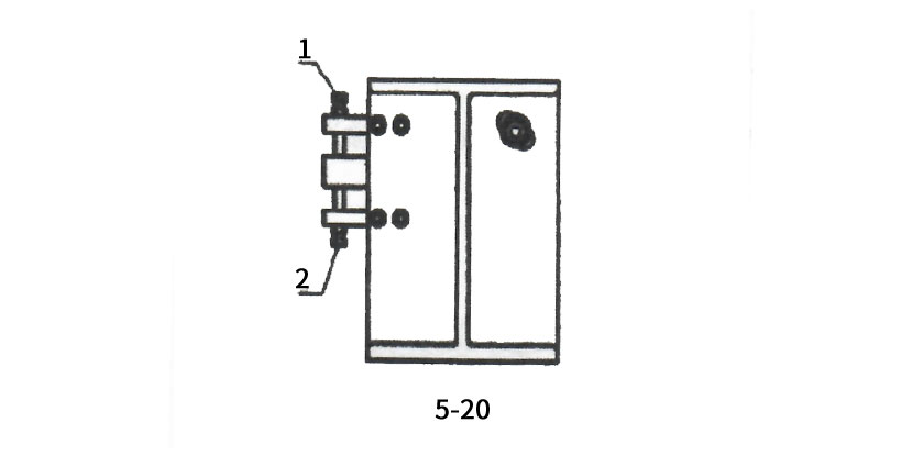
When it is found that there is no glue on the upper or lower surface of the wooden board after edge sealing, it is because the gluing roller is not perpendicular to the surface of the wooden board to be sealed. Adjustment method: When it is found that there is no glue on the upper surface of the wooden board after edge sealing, the gluing roller tilts the wooden board as shown in A in Figure 5-18, as shown in Figure 5-20. You can unscrew screw 2 and then screw in screw 1 to make the gluing roller perpendicular to the wooden board. When it is found that there is no glue on the lower surface of the wooden board after edge sealing, the gluing roller tilts the wooden board as shown in Figure 5-18 (B). Screw 1 can be turned back and screw 2 can be screwed in, indicating that the gluing roller is perpendicular to the wooden board. Repeatedly adjust screws 1 and 2 slightly until the upper and lower surfaces of the wooden board are evenly coated with adhesive after edge sealing.
(5) Adjustment of the belt feeding cut-off mechanism
The function of the feeding and cutting mechanism is to automatically pull out and cut off the edge banding strip required for the edge banding board from a roll of edge banding strips. The feeding and cutting mechanism can ensure the smooth and automatic conveying of the edge banding belt through adjustment, and can also adjust the distance between the bottom edge of the edge banding belt and the lower surface of the wooden board.
1. Adjustment of the distance between the lower surface of the edge banding strip and the lower surface of the wooden board
Adjusting the distance between the lower surface of the edge banding strip and the lower surface of the wooden board can ensure that the subsequent trimming function provides a certain amount of machining allowance.
Adjustment method:
(1) Loosen all four screws ① and ② in Figure 5-22;
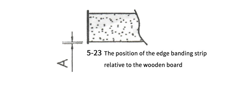
(2) Adjust the four set screws ③ ④ in Figure 5-22, and set the distance A between the lower surface of the edge banding strip and the lower surface of the wooden board (as shown in Figure 5-23) to 1~1 5mm, then adjust the conveyor panel to a horizontal position;
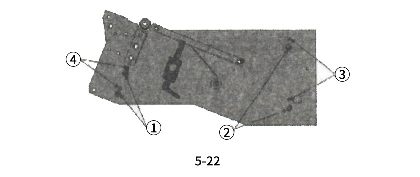
(3) Tighten screw 2 to secure the conveyor panel,
2. Adjustment of automatic belt feeding
In order to ensure the smooth delivery of the edge banding belt to the edge banding surface of the wooden board by the belt cutting mechanism, three steps need to be adjusted to ensure it.
The first step
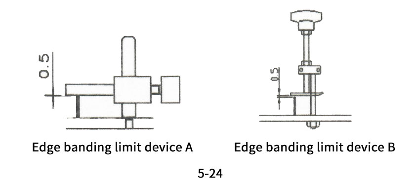
Set the clearance between the limit rod and the upper surface of the edge banding strip as shown in Figure 5-24, Part B, as shown in Figure 5-24, as approximately 0 5mm, allowing the edge band to pass smoothly without deviation. (Note: When replacing edge banding strips with different widths, adjustments must be made)
Section 2
Set the gap between the pressure block and the upper surface of the edge banding strip as shown in Figure 5-24 as approximately 0.5mm, so that the edge banding strip can pass smoothly without deviation. (Note: When replacing edge banding strips with different widths, adjustments must be made)
The third stage
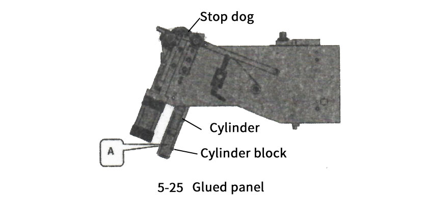
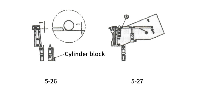
Loosen the fixing screws of the cylinder seat in Part A of Figure 5-25 as shown in Figure 5-26, and set the distance between the belt pulley and the stopper to Imm (initial setting) before turning on the belt feeding function. Then loosen the two screws A in Figure 5-27 and move the belt conveyor seat so that the edge banding belt can pass smoothly. (Note: Adjustments must be made when replacing edge banding strips with different thicknesses)
Attention: Before installing the edge banding belt and restarting the machine, ensure that the front end of the edge banding belt passes through the belt feeding wheel and does not exceed the cutting knife before the first wooden board edge banding, otherwise it may cause damage to some mechanisms during the first wooden board edge banding!
Inspection standards
The adhesive coated panel is 3mm higher than the conveyor chain plate;
Except for normal gluing, there should be no leakage at any other position of the rubber box as a whole;
Debugging and gluing requirements: The gluing amount should be 2400 x 50 in length, the board should be continuously fed, and the gluing panel should be evenly coated
The height between the adhesive coated panel and the base is 247 ± 0 5;
The parallelism between the adhesive coated panel and the feeding guide rail should be ≥ 0 in the longitudinal direction 05mm, transverse ≥ 0.10mm:
Stainless steel plate 1 is parallel to the adjustment plate, and the gap between the adjustment plate's up and down movement and the backup plate is ≥ 0 02mm;
The belt cutter moves flexibly back and forth, with a swinging gap of ≥ 0 02:
The distance between the blade back and the inner side of the blade holder is 53mm;
Belt cutting cylinder tail connection φ 8 air pipes, front end connection φ 12 trachea;
The tool holder and tool block should be installed in the same plane, and there should be no collision or scraping when the blade is moving;
Adjust the rubber door scraper. When the rubber door is closed, there is no gap between the scraper and the rubber roller, and the limit screw is under force;
When the rubber door is opened, the gap between the rubber scraper and the rubber roller is 0 5mm;
The gap between the rubber scraper and the upper support plate of the rubber roller is 0 02-0.03mm:
The bottom surface of the adhesive guide plate is parallel to the chain plate;
Adjust the rubber scraper cylinder, and the cylinder piston should be adjusted to the middle position of the cylinder block:
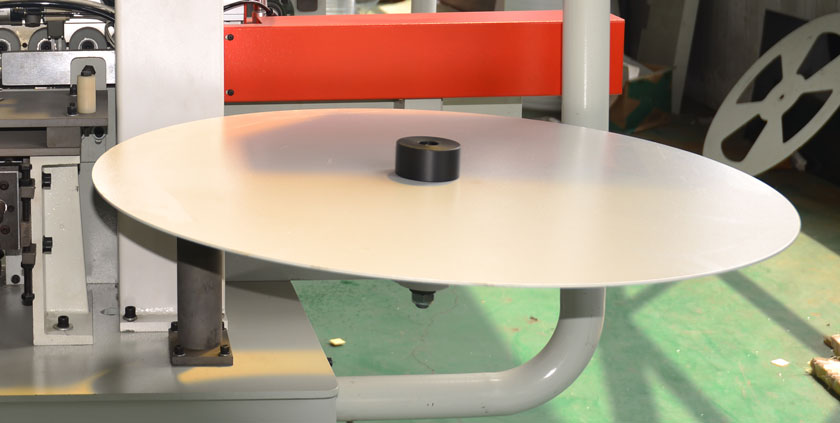
Install the disc and adhesive coated panel on the same horizontal plane:
The conveyor belt has no jamming or scratches during the conveying process, the conveyor channel is smooth, and each baffle is flexibly adjusted:
Flexible and reliable belt cutting;
Reserve a head and tail of about 3m;

 info@313mac.com