precision panel saw,edge banding machine

NewsHome > News

Edge banding machine mechanism debugging (4)-Disc components

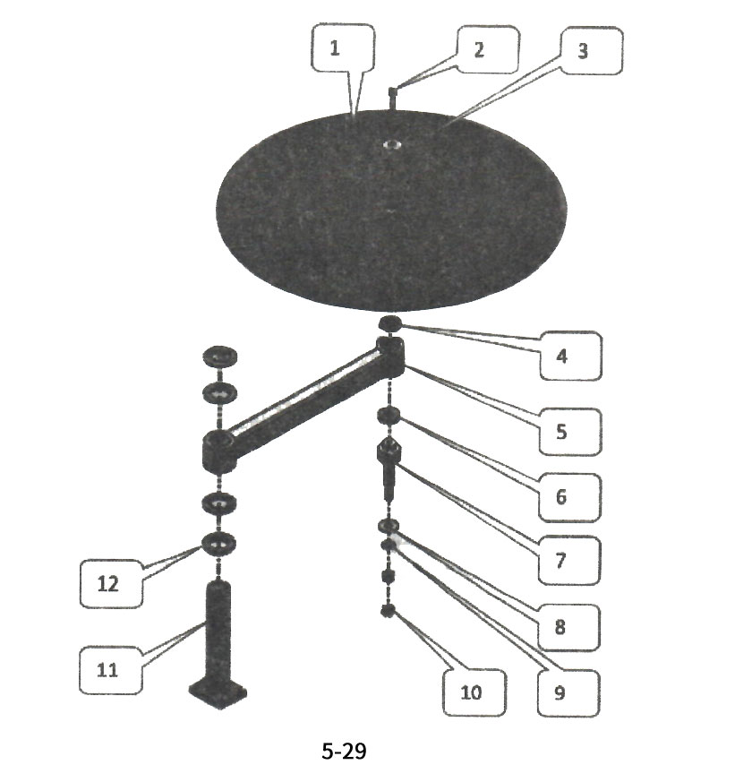
1. Introduction to the names of edge banding machine with disc components

Disc components

Disc components

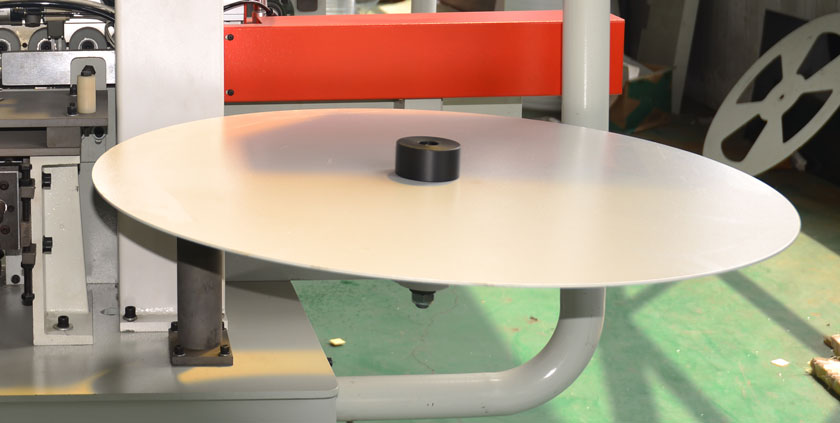
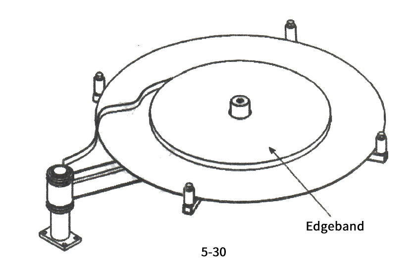
The disc mechanism is rotatable and used for placing edge banding strips. The disc surface is on the same plane as the adhesive coated plate, making it easier for the edge banding strips to be fed horizontally.
1) Putting on a disc
2) Hexagon socket screw
3) Locking shaft
4) Deep groove ball bearing
5) Bracket
6) Thrust ball bearing
7) Rotating shaft with disc
8) Belleville spring
9) Elastic washer
10) Outer hexagonal nut
11) Support tube
12) Round nut
2. The action process of the disc mechanism

The action process of the disc mechanism

Place the edge banding tape on the tape reel, and pass a section of the head through the gluing panel of the gluing mechanism (the tape should be on the same level as the panel), passing through the belt conveyor. The belt pulley starts to deliver the belt, pulls the belt pulley to rotate, and delivers the belt to the side of the wooden board; After the belt feeding is completed, the belt disc stops rotating and the belt is no longer fed. The belt cutting mechanism cuts the belt.
3. Debugging of disk mechanism
If it is difficult to turn the belt, it indicates that the nut in Figure 5-29 is locked too tightly. Loosen the nut by a certain point; If the belt is easily turned, it indicates that the nut is too loose. Just tighten the nut;
Rotate the circular nut shown in Figure 5-29 to adjust when the disc surface and the adhesive coated panel are not on the same horizontal plane.
Attention: Except for the edge banding tape, no other items should be placed on the tape reel to avoid unnecessary losses and casualties caused by spinning objects during the rotation of the tape reel.