Edge banding machine mechanism debugging (5)-Pressure strip components
1. Introduction to the names of edge banding machine components
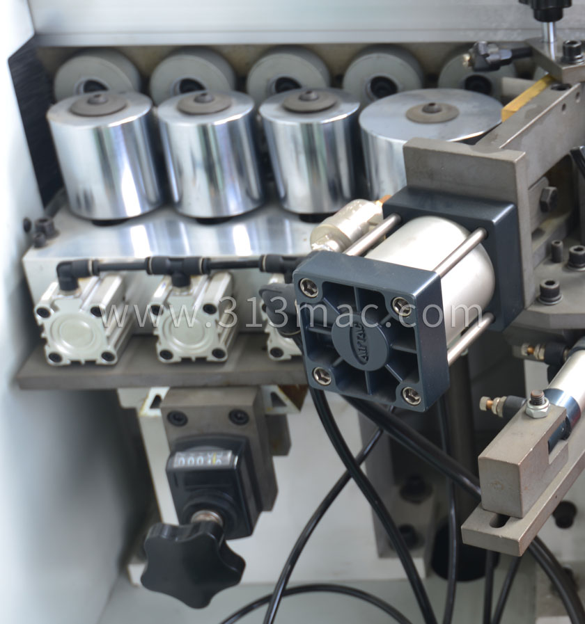
The function of the tape pressing mechanism is to press the edge banding strip onto the edge banding surface of the wooden board that has been coated with glue, and it can be adjusted to ensure that the edge banding strips of different thicknesses can be firmly and evenly bonded. Mainly composed of pressure rollers, cylinders, bases, etc.
2. The action process of the edge banding machine pressing mechanism
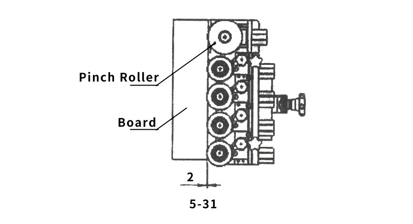
The vertical distance between each pressing wheel and the wooden board during standby and operation should be set at 2mm (the wooden board should be 2mm deep into the pressing wheel), which is more suitable (as shown in Figure 5-31). The working air pressure of the large pressing wheel should be set at 1kg, and the working air pressure of each small pressing wheel should be set at 2kg.
The air pressure of the small pressure belt pulley is 1.5-2.5 bar;
The air pressure of the high pressure belt pulley is 1.5-2.5 bar;
Feeding air pressure 2-4bar;
3. Debugging of the Belt Pressing Mechanism of the Edge Sealing Machine
When the tape pressing mechanism is in normal operation, when replacing edge banding strips with different thicknesses, simply select the corrugated handle on the tape pressing mechanism (as shown in Figure 5-31) to adjust the position display reading to the thickness size of the edge banding strip. If the thickness of the edge banding strip is 2mm, simply adjust the counter to 00200.
(Note: The second to last reading on the position display is in millimeters)
If, after the edge banding tape is pressed onto the board, it is observed from the upper or lower surface of the board that the edge banding tape is not fully bonded to the board, it indicates that the rotation axis of the pressure roller is not perpendicular to the surface of the board to be sealed. At this point, it can be adjusted to normal by adjusting the screws in Figure 5-34.
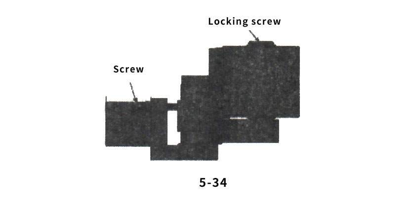
Adjustment method: first loosen the locking screw, and then adjust the screw. Use a wooden board for edge sealing. Carefully observe whether there is a gap between the pressure roller and the edge sealing strip when the wooden board passes through the large pressure roller and the last small pressure roller. Then observe whether the edge sealing strip on the wooden board is firmly bonded after the edge sealing is completed. By repeatedly sealing the wooden board and adjusting it, it can be adjusted normally. As shown in Figure 5-31, rotating the corrugated handle can adjust the large and small pressure wheels to move forward and backward together.
4. Inspection standard for edge banding machine pressing mechanism
1)The large pressure wheel is perpendicular to the adhesive coated panel;
2) When the large pressure wheel is running, the circular runout is not greater than 0.03
3)Debugging and pressing requirements: Inspect the edge banding strip according to the length of 2400X and thickness of 18 sheets, and press the edge banding strip 0.3X20 evenly up and down, with a deviation of not more than 0.25;
4) Test the short board, continuously feed 30 pieces, and there should be no jamming, leakage, uneven adhesive, or loose pressing;
5)The universal joint is flexible, and there is no abnormal noise in the gearbox and chain.
6)When the five pressure wheels are in the front position, the tangent point is on the same straight line (the cone pressure wheel is based on the small end being close to the edge), not more than 0.05mm:
7)The verticality between the large pressure wheel and the fourth and fifth small pressure wheels and the guide rail surface is not more than 0.03mm
8)The radial runout of all pressure rollers is not more than 0.02mm;
9)The swing of the pressure wheel after being subjected to force is not greater than 0.05mm;
10)The pressure roller operates flexibly without jamming;
11)The height between the bottom surface of the pressure roller and the base is 244.5 ± 0.5mm
12)Idle travel of front and rear adjusting handle ≯ 1/8 turn
13)The clearance between the sliding seat of the linear guide rail and the guide rail is not more than 0.05mm;
14)Fixing screws and dust covers for the linear guide rail

 office@313mac.com