Edge banding machine mechanism debugging (6)-End trimming component
The main function of the trimming mechanism of the edge banding machine is to cut off the excess edge banding tape that is pasted on the wooden board before and after, so that the two ends of the edge banding tape are flush with the front and rear end faces of the wooden board. When the thickness of the edge banding strip is not less than 2mm, certain chamfers can be cut at both ends of the edge banding strip according to the process requirements.
1. Introduction to the names of edge banding machine trimming parts
From Figure 5-37, it can be seen that the head and tail cutting components are composed of slide rails, sliders, motor components, bases, lifting seats, backup plates, dovetails, cylinders, etc. It can be divided into two components:
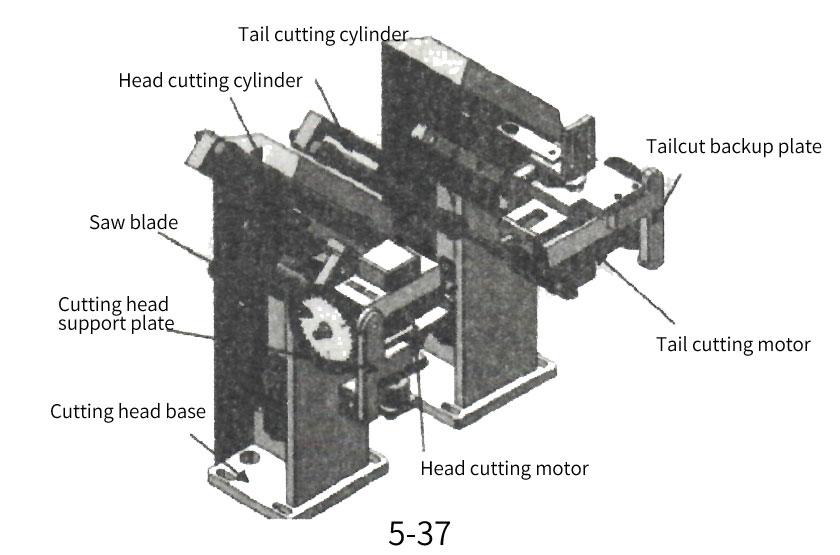
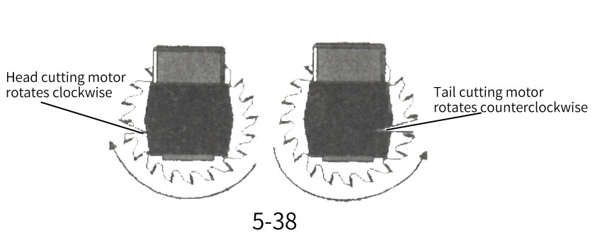
cutting head and cutting tail. The rotation directions of the head and tail cutting motors are different. The head cutting part motor shown in Figure 5-38 rotates clockwise and the tail cutting part rotates counterclockwise.
2. The working process of the trimming mechanism of the edge banding machine
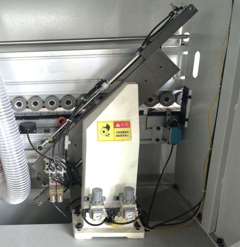
Cutting head air pressure display meter
① Head and tail cutting air pressure display table
R tail gas pressure display table
S-cut tail gas pressure regulating valve
T-cut head and tail total air pressure regulating valve
⑤ Cutting head air pressure regulating valve
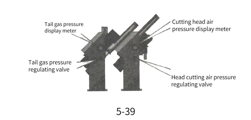
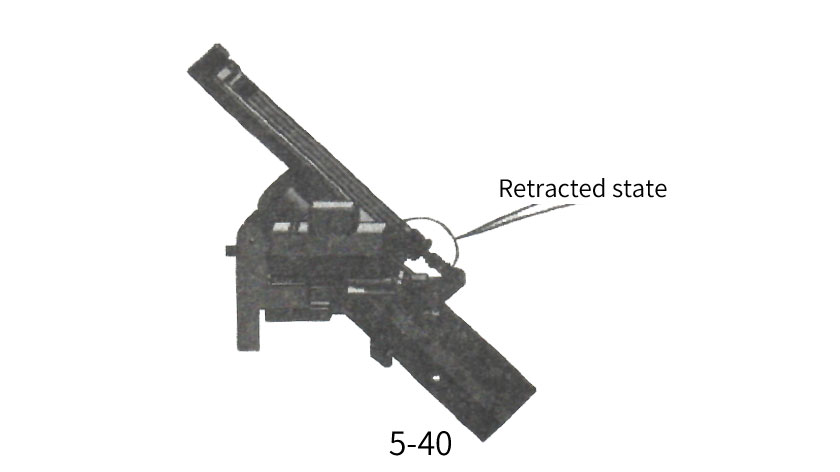
Under normal circumstances, the standard value of the barometer ① is 0.5-2bar; The standard value of barometer ② is 2-3bar, while the standard value of barometer ③ is 0.5-2bar. After the air pressure is applied to the head and tail cutting components, the head and tail cutting preparations begin. The two saw blades begin to rotate at high speed, and the original state of both cylinders is in a retracted state.
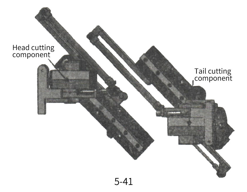
The working process of the head and tail cutting mechanism is shown in Figure 5-41. When the wooden board touches the travel switch, the head and tail cutting mechanism enters the working state. The wooden board moves with the conveyor chain board, and the front end of the wooden board contacts the working surface of the cutting head. The cutting head part is pushed forward, and the cutting head saw blade quickly (much faster than the movement speed of the wooden board) slides down to remove excess edge banding, waiting for the position where the belt is crushed;
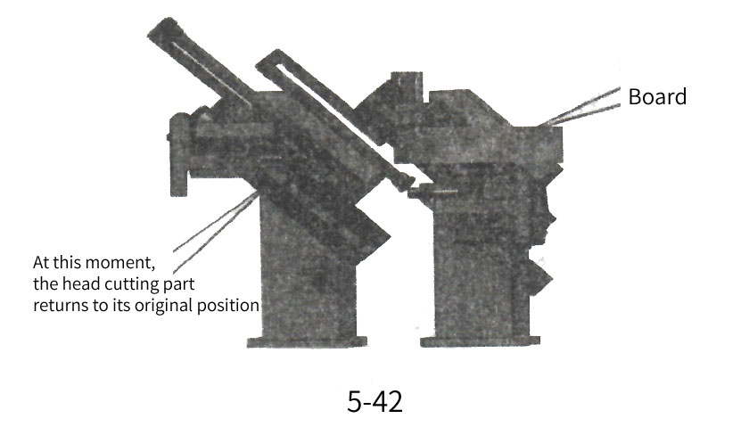
When the wooden board reaches the position shown in Figure 5-42, the cutting head quickly returns (the cylinder is in a retracted state).
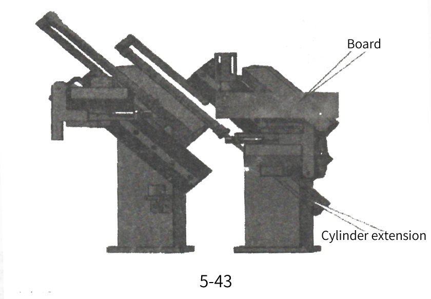
The board continues to move forward, and when the board is cut against the tail board, the tail saw blade instantly cuts off the excess edge banding at the end of the board, as shown in Figure 5-43. After the cutting action is completed, the tail cutting mechanism is reset, and the work of the head and tail cutting mechanism is now completed. This cycle works.
3. Debugging method for edge banding machine trimming
The adjustment of the perpendicularity between the cutting head and cutting tail backup plate and the processed wooden board, as shown in Figure 5-44, can be achieved by loosening the screws, moving the guide rail, and repeatedly moving the guide rail slightly until the wooden board is perpendicular to the cutting head (or cutting tail) backup plate
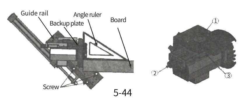
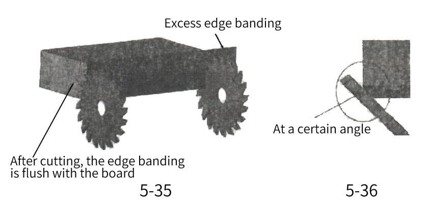
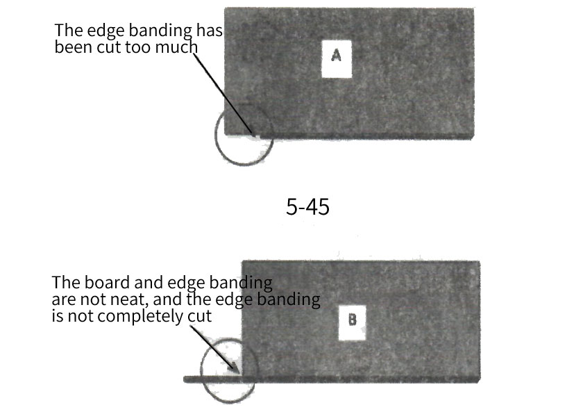
After the head and tail cutting process is completed, if there is still residual edge banding as shown in A in Figure 5-45, tighten the screw ③ in Figure 5-45 and rotate the motor stroke adjustment screw ② counterclockwise to move the motor forward; On the contrary, if the wooden board shows phenomenon B as shown in Figure 5-45, and the edge banding belt is cut too much, it can be adjusted by rotating the motor stroke adjustment screw ② in Figure 9-10 clockwise. By repeatedly fine adjusting, until a satisfactory cutting effect is achieved.
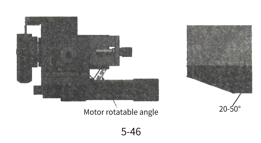
At the same time, the angle between the motor and the tail cutting slide plate can also be adjusted to obtain the head and tail cutting effect shown in Figures 5-45, A and B. Loosen screw ① in Figure 5-44, rotate and move the entire cutting tail (or cutting head) component left and right according to the desired angle until the required angle is reached. Finally, tighten screw ① and lock the dovetail. Starting from when the motor is parallel to the cylinder, the maximum angle that the saw blade can adjust outward is about 20.56 (as shown in Figure 5-46).
Attention: After daily use, please use a blowing pipe to clean the sawdust and add maintenance oil to keep the dovetail and moving guide rails clean at all times.
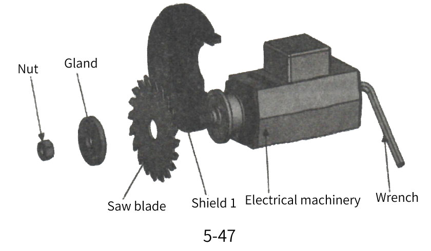
4. Replacement of edge banding machine end trimming saw blade
When the saw blade becomes dull, it should be replaced in a timely manner. As shown in Figure 5-47, use a hexagonal wrench to firmly hold the rear end of the motor, loosen the nut at the front end of the motor, take out the gland and saw blade, replace them with a new saw blade (pay attention to the rotation direction of the motor and saw blade), and install them. Press the gland lock nut tightly. (Pay attention to evenly applying a layer of lubricating oil on the contact surface with relative motion)

 info@313mac.com